-
How to print PLA on glass?
When I got my first 3D Printer (Malyan M150) and got into 3D printing I was surprised how consumer not-ready technology this is. Sticking, not sticking, overextrusion, underextrusion, Kepton, blue painters tape, clogged extruder... Over the time, at least, I was able to get the whole 3D Printing process somehow repeatable. I think one of the most important changes I've made in my 3D Printing experience is to ditch Kepton and blue painters tape in favor of printing PLA on glass. Process got simpler, faster and with better results. Also, not counting initial investment, cheaper.
-
Detecting Cleanflight PID tuning issues with Blackbox: gyro noise
After a short brake, let's return to Blackbox series with new entry: "How much gyro noise is too much?".
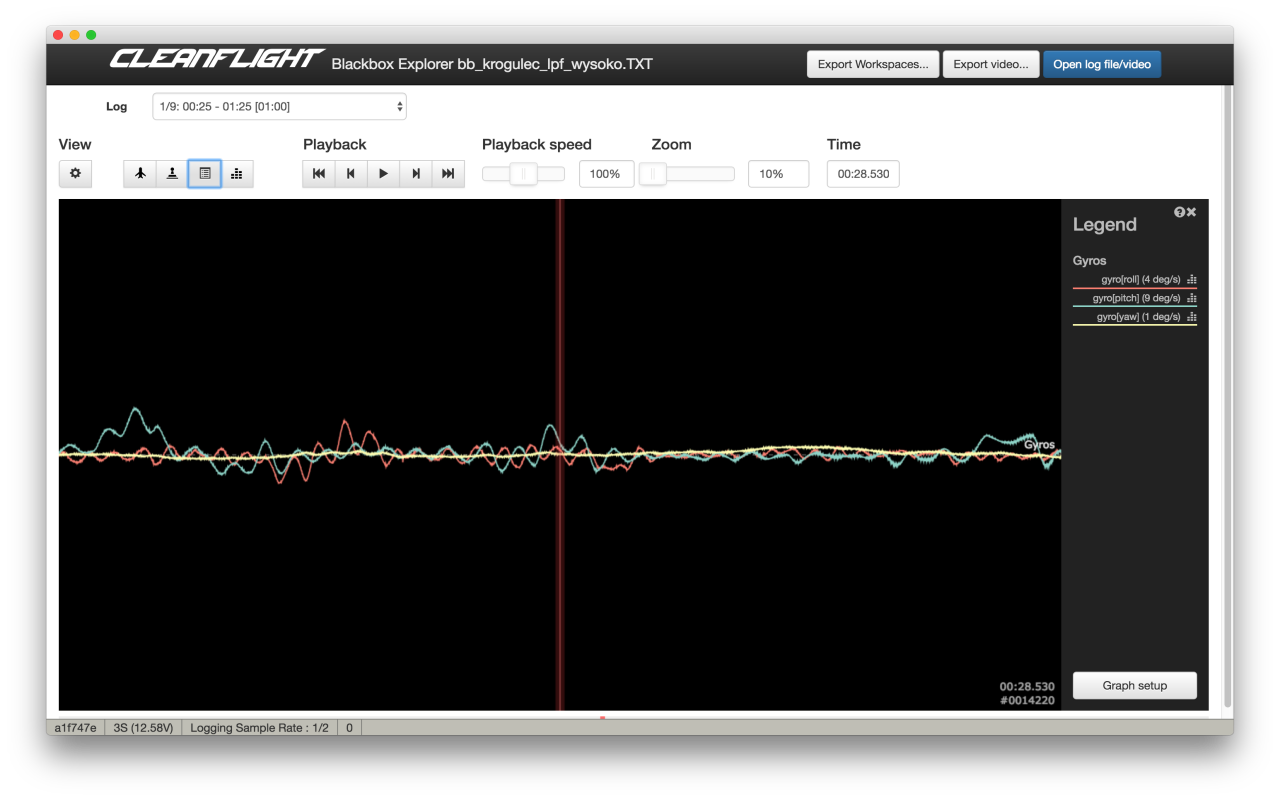
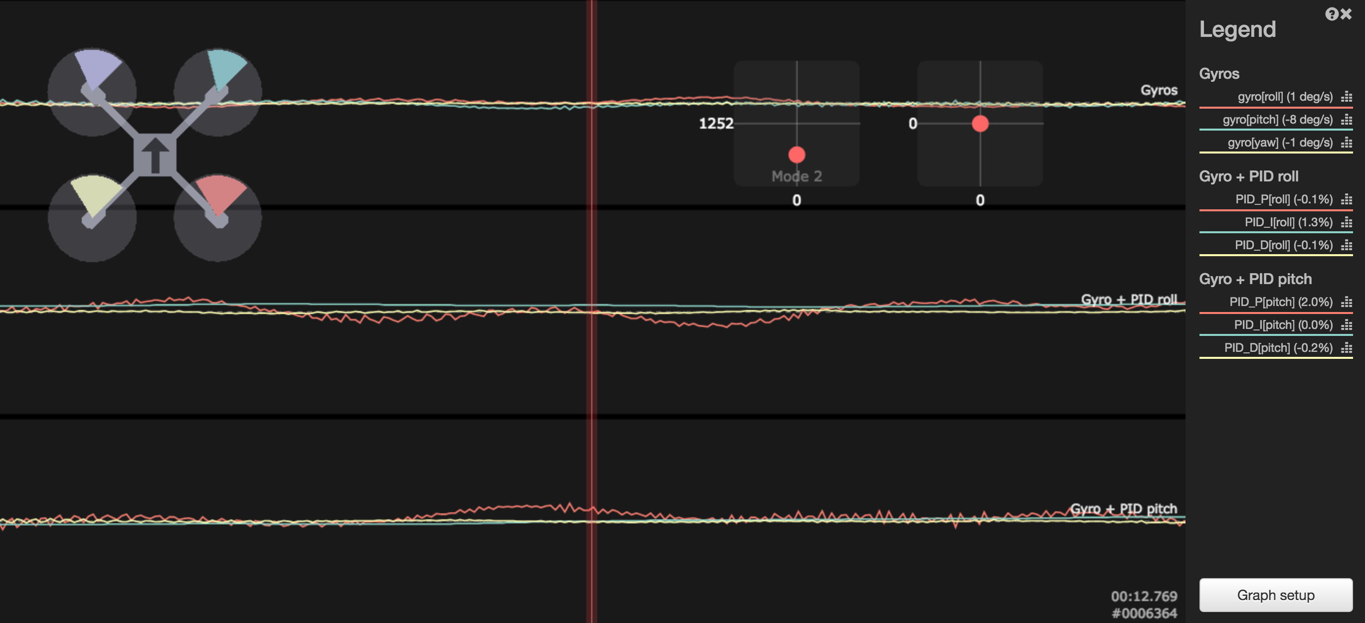
Almost all PID tuning tutorials states: reduce vibrations that affects gyroscope and accelerometer readouts. Yes, this true: any vibrations that appear during flight affects gyroscope and accelerometer readouts are bad and should be kept as low as possible. This can be done by balancing motors, propellers, using stiffer frame, adding dampeners, lowering LPF filters. But how much vibration induced gyro noise is too much? Let me answer with four Blackbox screenshots:
Super smooth gyro traces, no noise

This is how it should looks like! Perfect trace. If it is archived without lowered LPF filters, then kudos for balancing everything!
Somehow noisy gyro traces
Little noise appears, but amplitude is low, everything is under control.
Noisy gyro traces
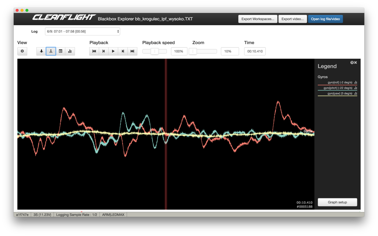
Gyro noise is visible. It is not a problem yet. If it was a result of raised LPF cutoff frequency, extra noise might be worth lowered signal delay. I would start to think how to reduce it on a hardware level. Perhaps bearings are dying, or propellers should be rebalanced?
Extremely noisy gyro traces
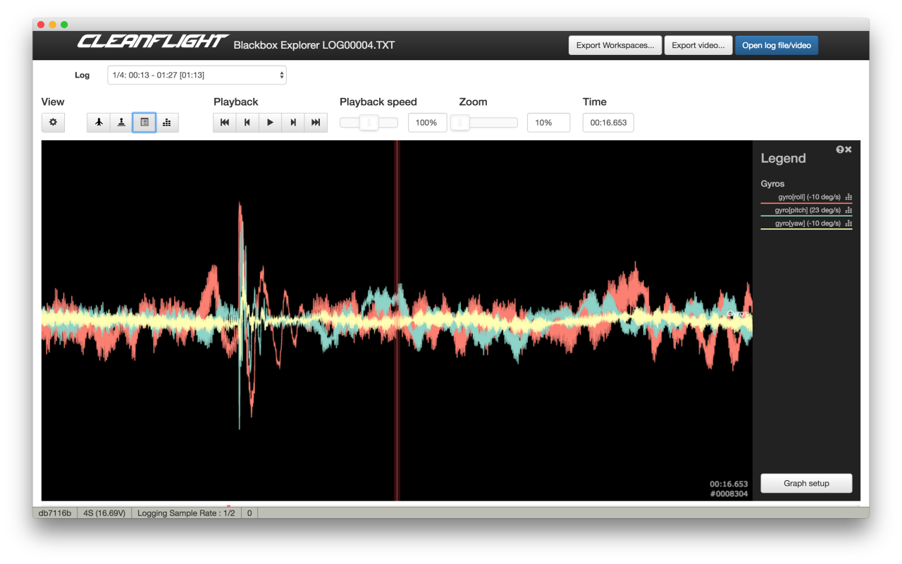
This is how unflyable gyro noise level looks like! If you see have problems with flight performance, you know what is causing it. This have to be fixed ASAP before everything else.
Read more... -
How to tune PID I-term on a quadcopter
With this entry I want to initiate short series of articles showing how to tune multirotor / quadcopter PID controller. Let's call it a continuation of Blackbox series, but this time I will not relay only on Blackbox data. Yes, I will show few examples how given scenarios looks on Blackbox logs, but all steps will be doable without Blackbox.
Before we proceed, you much understand how PID controller works and what
Kp aka. P-gain,Ki aka. I-gainandKd aka. D-gainare responsible for. There are many sources: Wikipedia, my "What is PID controller article", great video from Bruce and many many others.How to tune I-term of PID controller
Most PID tuning tutorials suggests to start with P tuning and then move to I. Why? Probably because it's simpler to get UAV in flyable state. Or because P is first letter on PID. Or I have no idea. Starting with I has some advantages:
- tuned I-term will not affect much more important Pterm tuning
- it is simpler to tune I than P if proper method is used
- tuned I-term will probably not change during P and D tuning
Before we proceed, a reminder of what
I-termis used for and short characteristic of it:- I-term is responsible for correcting long time error accumulated in the past: non-even thrust from motors, wind, etc.
- I-term should not be affected by short events like few degrees attitude correction
- I-term should should react fast in special conditions like upside-down phase of rolls and flips
- bigger I-gain not only means that correction will be stronger. What is more important, it also determines how fast I-term would change!
- too low I-term causes multirotor unable to keep desired attitude. UAV will bank on its own, be sensitive to wind
- too much I-term will introduce overshot, visible low frequency oscillations, wobble on descend
- gentle, smooth flying for aerial photography requires much lower I-gain than aggressive acrobatic flight
- better UAV balance (center of thrust close to center of gravity) results in lower required I-gain
- usually, due to weight distribution, pitch axis requires more I-gain than roll axis
There are two methods of manual I-gain tuning:
- Tuning for smooth, aerial photography, flying with bigger drones
- Tuning for acrobatic flying with smaller drones (250 size and smaller)
How to tune I-term for smooth flying, aerial photography style
General rule for I-gain tuning for smooth flying on bigger machines (8" or bigger propellers, > 1kg) is to keep
Ias low as possible. Multirotors like these are not designed for acrobatics, or aggressive flying. Their main purpose to to be stable in hover or cruise and do not wobble on descend. Higher I-gain, due to bigger (sometimes huge) inertia of both body and propellers will result in overshooting, wobbles and oscillations.- Start with weight balance. Center of gravity should be as close as possible to point of thrust. Simple procedure looks like this:
- For pitch and roll axis find a line that crosses the frame between two point lying in the middle between motors opposing this line
- Try to lift multirotor using two fingers catching centerplate where line crosses it
- If frame tilts forward, move some weight (usually battery) back, if frame tilts left, move some weight right, and so on
- This does not have to perfect, but the closer you will get, the better flight performance you will have
- Tune roll and pitch separately. Ignore yaw for now, this can be tuned much later and usually it is not required to tune yaw at all!
- Tuning has to be done in Acro/Rate mode, without self leveling!
- Start with default PID gains. In most cases they are good enough for hover. If drone is able to take off and does not wobble on its own, you are good to go. If it is sluggish, wobbles, tilts on its own, increase P gain in 20% steps until it is hovering without much trouble. Remember, we are not tuning P yet. We just want it to be flyable.
- Throttle up and do a fast ascend for few meters. Then cut throttle to about 25% and descend fast. Observe what is happening to a drone. Three things can happen:
- If drone is unable to keep attitude and tilts is any directions, I gain on this axis is too low. Increase I gain and repeat experiment
- If drone keeps attitude, but wobbles on descend, I gain is too high. Decrease I gain and repeat
- Try to keep I gain lower than higher. That means you should concentrate on finding a spot closer to a point where UAV is unable to keep attitude that to the point where wobble appears
- If drone keeps attitude and does not wobbles on descend, I gain is tuned
- Confirm I-gain tune by doing forward-backward and left-right fast flights. If multirotor is able to keep angles, does not slowly drift or slowly wobbles during braking, congratulations, you tuned I-gain for smooth flying!
On a Blackbox log, wobble during fast descend might look like this:
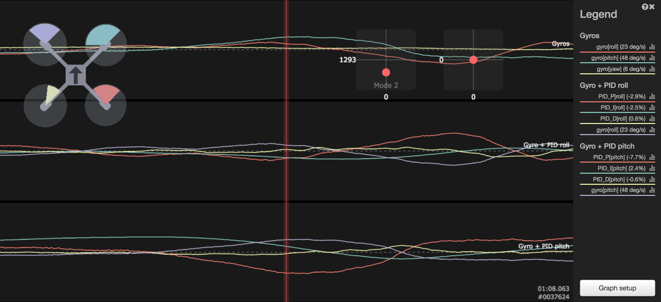
Both axises: roll and pitch were affected in this case, but bigger wobble appeared on pitch axis, up to 45degrees per second! If you take a look at pitch PID graphs, you would see that I-term moved from more positive, to negative and then to positive again.
P termtried to compensate, but it had to fight not only with changing conditions, but also with changing I term after original movement has been canceled out. This might not a be a perfect example, but shows general principle.This example show what is happening in similar situation when I gain is much lower. I term stays more less flat, most of the work is done by P term.
How to tune I-term for acrobatic flying
If you would tune I gain using procedure from previous paragraph and went doing some rolls and flips, you would notice something bad: when copter crosses 90 degrees and begins upside-down phase, single wobble, a strong jerk, appears. Like I mentioned before, I gain does not only determines correction force. It also determines allowed speed of change when conditions changes. Imagine a copter that is slightly tail heavy. That means motors in the back have to spin slightly faster than those in the front to compensate for weight imbalance. I term does that very moment you take off and it works as long as you do not try to bring everything upside down very fast. If rear motors would still bring more trust that forward motors when drone is inverted, it would not compensate for weight imbalance. It would make thing worse than better. Our imaginary tail heavy multirotor needs less thrust in the back when flying inverted.
Flips, rolls and all other rapid maneuvers requires higher I gain to allow for faster I term change. If I term is unable to follow strong changes, single wobble or multiple wobbles would appear when passing magical 90 degrees inclination.
Another problem with method from previous paragraph is that small machines are much more wobble on descent resistant than big ones. Smaller, faster rotating propellers, less inertia, more agile. One would really have to push I gain very high to see strong wobble during descend. And it still not would do good for acrobatics. This is why, on those machines, try the following
- Balance multirotor like above
- Start with default PIDs
- Use only Acro/Rate mode
- Tune each axis separately
- Take off and check UAV stability during fast ascends and descends
- If it keep attitude but wobbles, lower I gain
- If it does not wobbles, but does not keep inclination, rise I gain
- If it does not wobbles and keeps attitude, we can move forward
- This step does not have to be very precise. As long and it keep inclination, you are good to go
- Go high. If you have FPV, this helps a lot. If not, just pay attention to drones behavior
- Do a fast single roll. If during transition to inverted flight (around 90 degrees) multirotor jerked, I gain is too low and I term is unable to follow the change. Raise I gain on axis and try again. The hardest thing here is to decide which axis is responsible for jerk. Sometimes it is single axis, sometimes both roll and pitch together: FPV helps a lot with this. If you really do not know, rise both. Repeat this step until roll is smooth, without visible wobble
- Do the same during flips. If you did everything right in previous step, this is only to confirm everything works like expected
- Confirm there are no wobbles during fast descends. If they appear try lowering I gains a little
Small note: I gain that allows for smooth transition to inverted flight flight depends on rotation speed and imbalance. The bigger imbalance and faster the rotation, the higher I gain would be required. So if you change rates, you might want to repeat I term tuning.
Read more... -
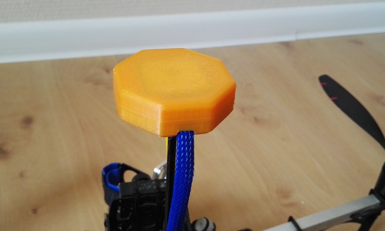
Flight controller 30.5mm to 45mm mount adapter
Almost all "racing" MultiWii derivatives flight controllers like Naze32, SPRacingF3, CC3D or Sparky, besides the same CPU family (STM32) and ability to run Cleanflight, share the same form factor: 36x36mm size and 30.5mm hole spacing.
That creates a small problem when mounting them to some bigger frames designed to fit APM, Pixhawk or MultiWii. They do not fit and require additional adapters.
Facing problem like this, I've designed simple 3D Printed 30.5mm to 45mm flight controller adapter.
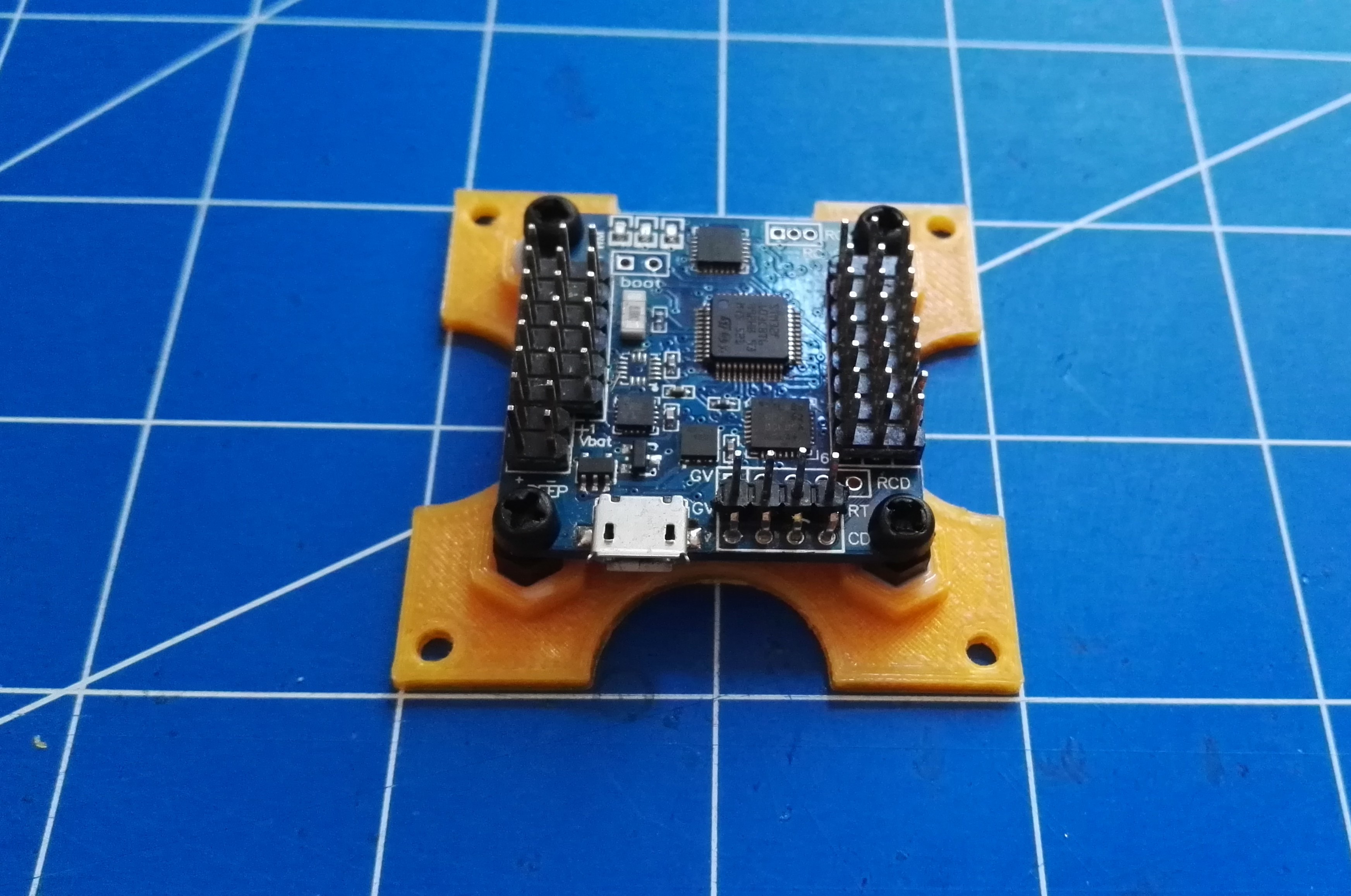
To use, 4 hexagonal nylon M3 standoffs have to be glued into place. M3 thread is rather too small to print on most 3D printers. It's just faster and simpler to glue standoffs than try to print threaded holes. I used epoxy glue, but hot glue also can be used if needed.
Read more... -
How to reverse motor direction
You finished your build, you connect LiPo, power up flight controller, apply throttle (no propellers of course) and you see that one or motors are spinning in wrong direction. How to fix that? You can not do it, for example in Cleanflight Configurator. ESC communication protocol does not allow to change BLC motor direction.
There are 4 ways of dealing with this problem:
- Hardware way that works all the time: swap any two motor wires. Does not matter which, just take any two and swap them between motor and ESC: A with B, B with C or A with C. If you have bullet connectors, it's simple. If you soldered wires to ESC pads, you would have to resolder them.
- If you have BLHeli ESC software, BLHeliSuite allows to change motor direction without swapping any wires. Connect to ESC with BLHeliSuite, and change Motor Direction option.
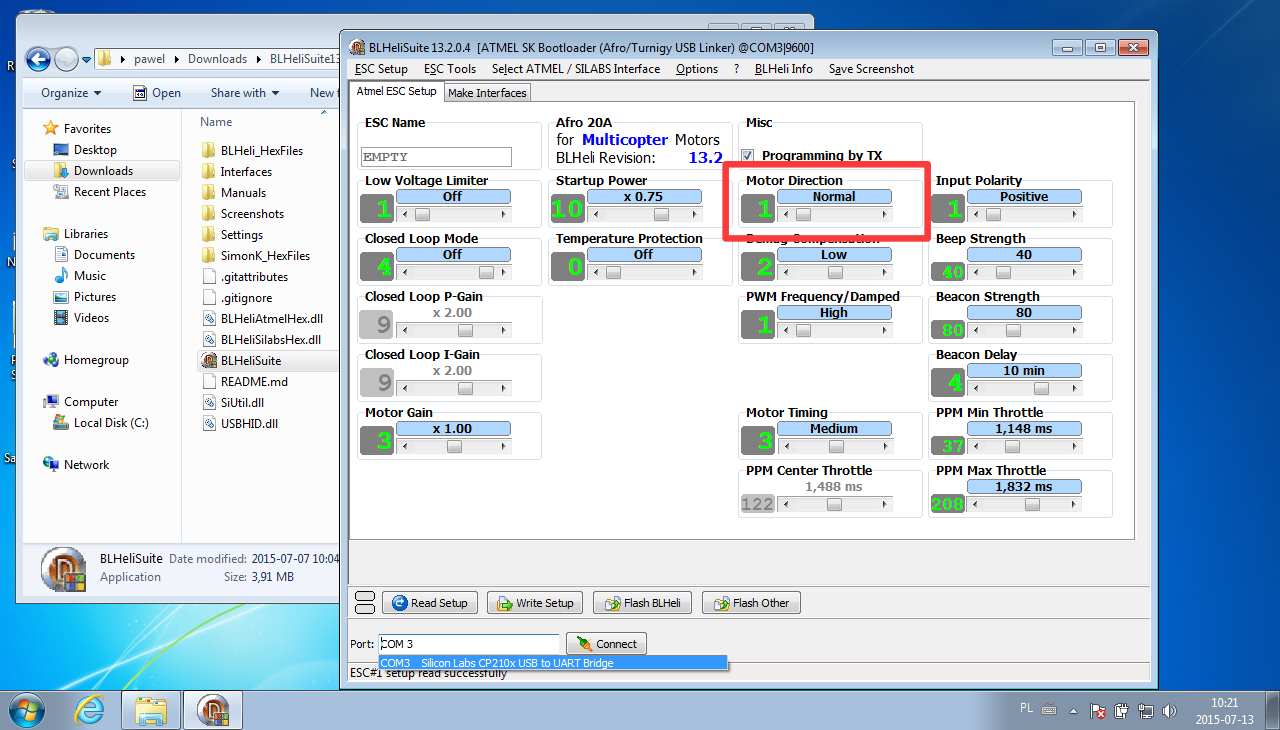 This works only with BLHeli enabled ESC, and only on Windows.
 - Most of ESC allows to change options like motor direction via transmitter. Exact procedure differs from manufacturer to manufacturer, but usually it looks like below. For exact procedure and possible options refer to ESC user manual!
- Connect ESC to radio receiver throttle channel or use flight controller configurator software Live mode. Remember to remove propellers!
- Throttle UP
- Power ESC, it will start to beep signaling number of cells
- Keep throttle up until you hear a sequence that confirms programming mode has been entered
- Wait to hear beeping sequence indicating Motor Direction option
- Throttle DOWN
- Wait until you hear beeping sequence indicating desired rotation direction (normal or reversed)
- Throttle UP
- Setting will be changed and after next power cycle rotation direction will be changed
- Sometimes special programming cards for ESC can be acquired. They somehow automate procedure from point 3 but work on the same principle. For exact programming procedure refer to programming card user manual.
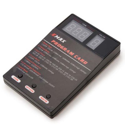
EMAX programming card photo [1]
Read more... - Hardware way that works all the time: swap any two motor wires. Does not matter which, just take any two and swap them between motor and ESC: A with B, B with C or A with C. If you have bullet connectors, it's simple. If you soldered wires to ESC pads, you would have to resolder them.
-
Which sensors drones use to fly?
Modern drones utilize many different sensors to archive flight. Some of them are required to fly, some are only optional and they can only improve flight performance. This entry will be a summary of those sensors, with short description and information how UAV utilizes data from them.
Gyroscope
Gyroscope, or shorter gyro, is the only sensor that drone really needs for stable flight. It feeds flight controller with extremely important information: how fast aircraft is rotating around its own axises: roll, pitch and yaw. Inner loop of PID controller utilizes his information to stabilize the craft.
When pilot is not applying any deflection to roll, pitch and yaw control sticks (they are in neutral positions), drone should not rotate. It should keep current attitude, do not wobble, do not have rotation drift. If it starts to rotate, this information is taken from gyros and counteraction is applied to stop unintended rotation and event to rotate back to desired attitude.
-
Cleanflight low pass filters part 2
Quite a lot things changed in the world of low pass filtering since my previous port on this topic was published. So, here is the updated guide to Cleanflight LPF filters:
gyro_lpf
gyro_lpfis the most important low pass filter for gyroscope readouts. First of all, it is not part of Cleanflight, but is done by gyroscope itself. Cleanflight only initializes gyro with desired cutoff frequency. Allowed values are:- OFF
- 188HZ
- 98HZ
- 42HZ
- 20HZ
- 10HZ
When
OFFis selected, gyro offers fastest possible sampling rate (8kHz, new data every 125us) and smaller possible delay. But, it is extremely prone to any vibrations. Any noise from motor or propeller will be visible in gyro output. All other values of this filter allows gyro to provide new data every 1000us (1kHz).42Hz is lowest 'flyable' cutoff frequency. It does not makes sense to go lower, since signal delay will be too big and filter will attenuate frequencies that are important from 'flight' point of view. So, 188Hz, 98Hz and 42Hz are the ones that are interesting for us. Exact value depends on propellers, motors, balancing, bearings state, frame rigidness and few other aspects. Let's say, that 250mm or smaller frames can use 188Hz, 450mm and bigger frames should use 98Hz or 42Hz.
gyro_soft_lpf
gyro_soft_lpfis a second state of gyro readout filtering before they are introduced to PID controller. One might ask: why two filters? After all,gyro_lpfdoes the same thing. Yes, it does the same thing. But using 2 LPFs in this case has some advantages.gyro_lpfcan not be tuned. It's either: off, 188Hz, 98Hz, 42Hz. But what if, for example, main source of gyro noise is at about 90Hz? Cutoff at 98Hz would be pretty useless. One would have to use 42Hz, loosing a lot of usable frequencies and having to suffer from noticeable (from PID controller point of view) delay. This is why fully configurable second stage of LPF was added.gyro_soft_lpfshould be kept belowgyro_lpf, and below frequency of main noise source. Usually between 50 and 100Hz. Frequencies below 50Hz are too important for stable flight to attenuate them. On the other hand, everything above 100Hz is useless and can be cut off.pterm_cut_hz
This software LPF filter was removed and is no longer available.
dterm_cut_hz
Here, let me just quote my previous post:
(..) D term of PID controller, since it is trying to look into a future, can be a source of huge noise and vibrations. After all, looking into a future is always a tricky business. This is why D term can change with totally different frequency than gyro input and there is a very good reason to limit D term change. Too see how excess D noise can affect gyro traces take a look at my Blackbox tutorial.
(...) Rule of thumb is: smaller and more rigid frames allows for higher D term cutoff frequency and 42Hz is a good place to start. Bigger frames might require lower cutoff frequency and 10Hz is lower boundary.If only frame and noise level allows, D term cutoff frequency should be kept as high as possible. This allows D term to reacts faster to changing flight conditions and can greatly improve UAV behavior in prop wash and rapid maneuvers.
Read more... -
How to cut Depron
Depron is an amazing material. Light, cheap, waterproof, easy to process and quite durable. Almost everything in RC world can be made from Depron. All one needs is imagination, glue and proper knife. Like I mentioned few times before, I'm cheap, so at the beginning of my adventure with Depron, I was choosing cheap modeling knives. Usually no-name. They had one very serious flaw: knife's blade had to be replaced every few cuts. And even so, cut was far from perfect.
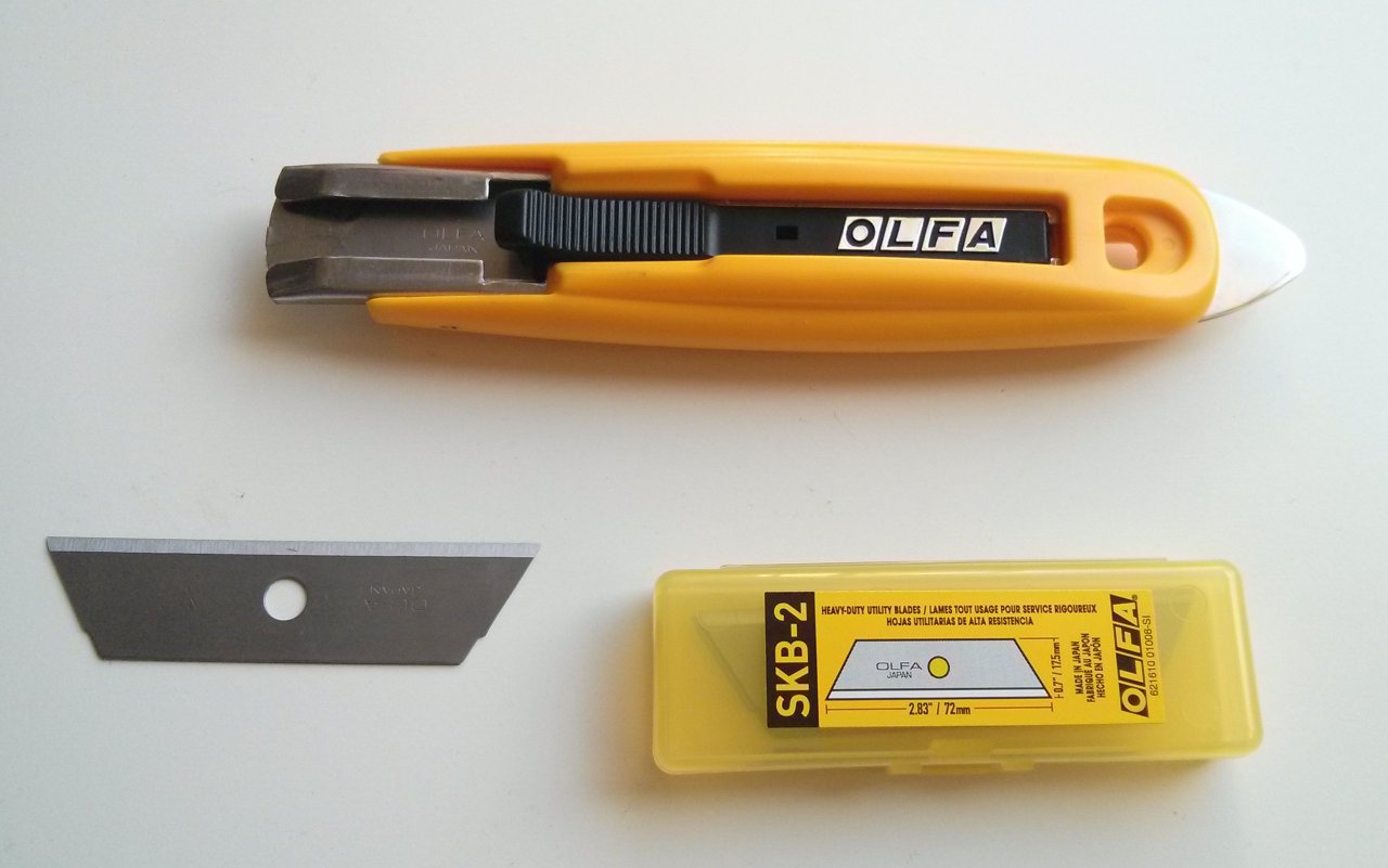
Luckily, I've found a perfect, more expensive but cheaper on a long run, solution: Olfa Knives. Especially Olfa SK-9 Knife with SKB-2 Blades. They are sharp, strong and lasts for a long time. When needed, SKB-2 blade can be used without a knife. SK-9 has one disadvantage: there is no lock, so keeping blade extended all the time requires thumb to be used. And that make it hard to switch knife between hands.
But the bottom line is: I love Olfa knives. Not only when working with Depron. They are very useful with dealing with cables, unpacking and so on...
Read more... -
Beitian BN-880 GPS 3D Printed Case
Beitian BN-880 (I've bought mine from Banggood) is an excellent, cheap and accurate Ublox NEO-M8N GPS module. I'm using it for last few months and I'm very happy with it. But is has one serious flaw: there are no cases/enclosures for it. So, in most applications it is naked. I've decided to fix that and designed 3D printed Beitian BN-880 case.
Case can be dowloaded from Thingverse
Read more... -
850m for $20
Short update on my DIY telemetry link for $20 from my previous post. In theory, it should be able to work up to 500m. Today I archived range of 850m. And I'm pretty sure it's not the end if I was flying higher. At this distance signal was attenuated by 1st Fresnel zone. Next time, more altitude and higher mounted receiver antenna!
Read more...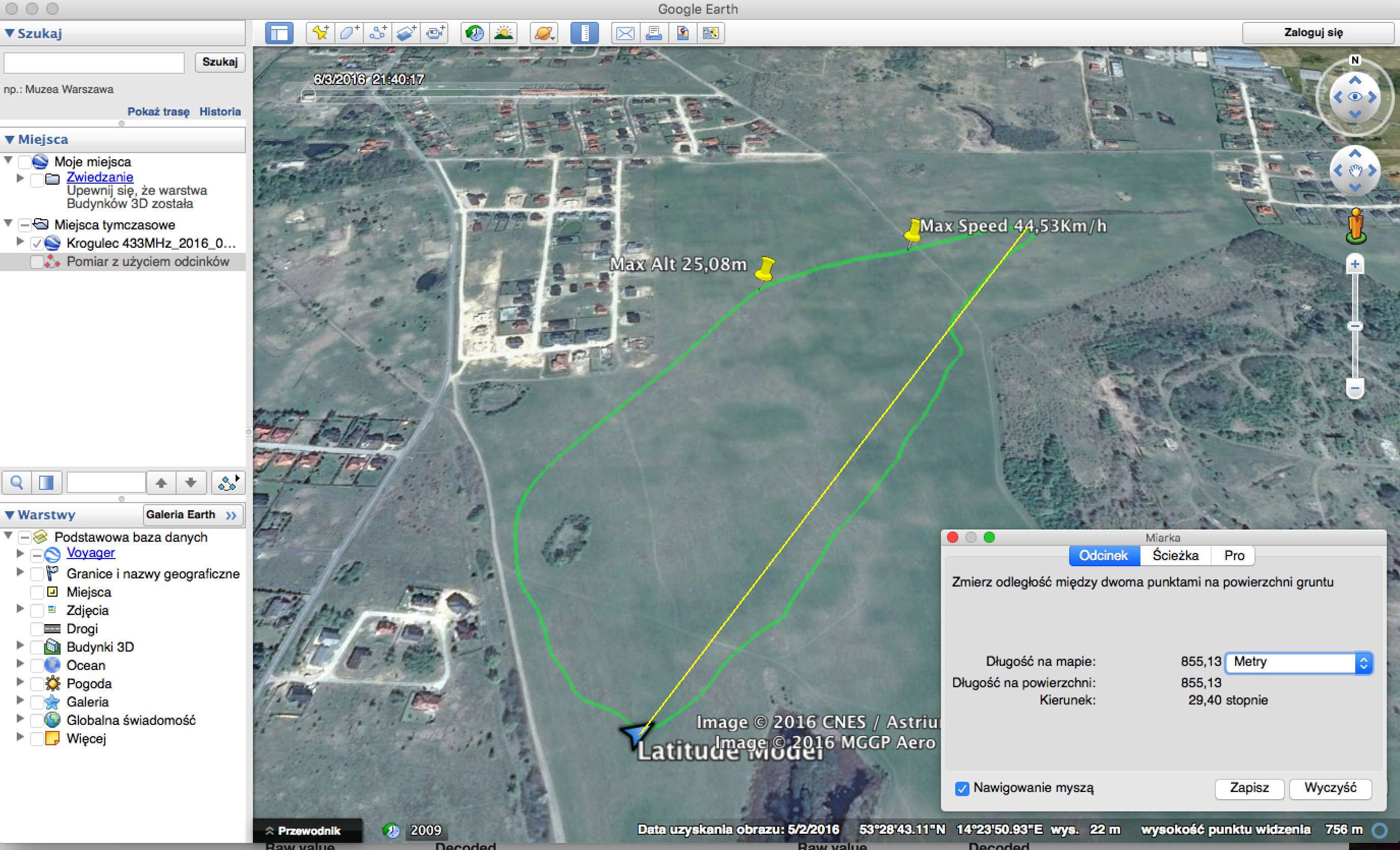


I'm Paweł Spychalski and I do things. Mainly software development, FPV drones and amateur cinematography. Here are my YouTube channels: